Documentation
Complete guide to designing, building, and using your OpenTouch Gloves.
Design Your Custom Glove
Use our jupyter notebook to make a custom design for your own hand: instructions and repository.
Details of the design algorithm are in our paper
Order Components
Readout Circuit
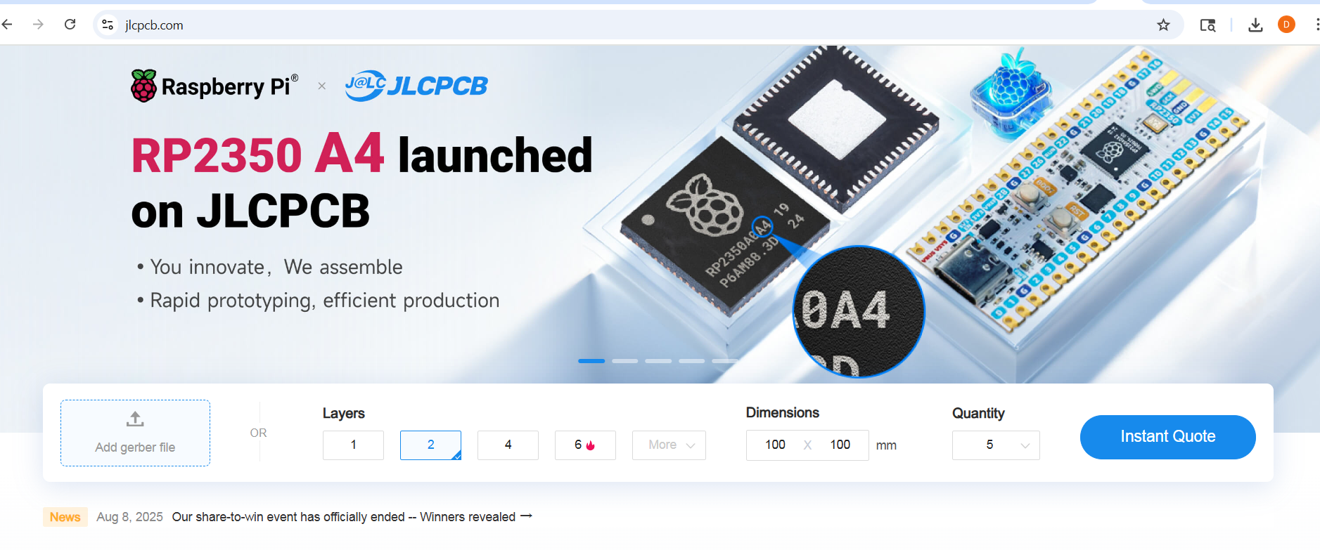
The OpenTouch Gloves use a zero-potential scanning readout circuit (shown to reduce cross talk between electrodes in resistive sensing arrays). You can order the circuits fully assembled (minus the header pins) from JLCPCB.
-
Enter the number of boards you'd like to order under "PCB Qty" (you need one for each glove).
-
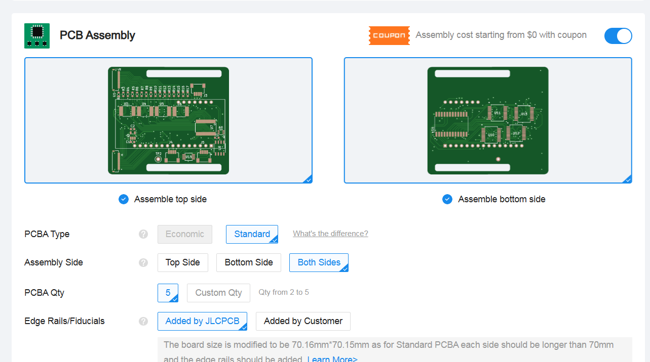
The other default settings are fine. Scroll down to PCB Assembly. And select "Standard" for PCBA type and "Both sides' for assembly side
-
Select desired build time and click "Next"
-
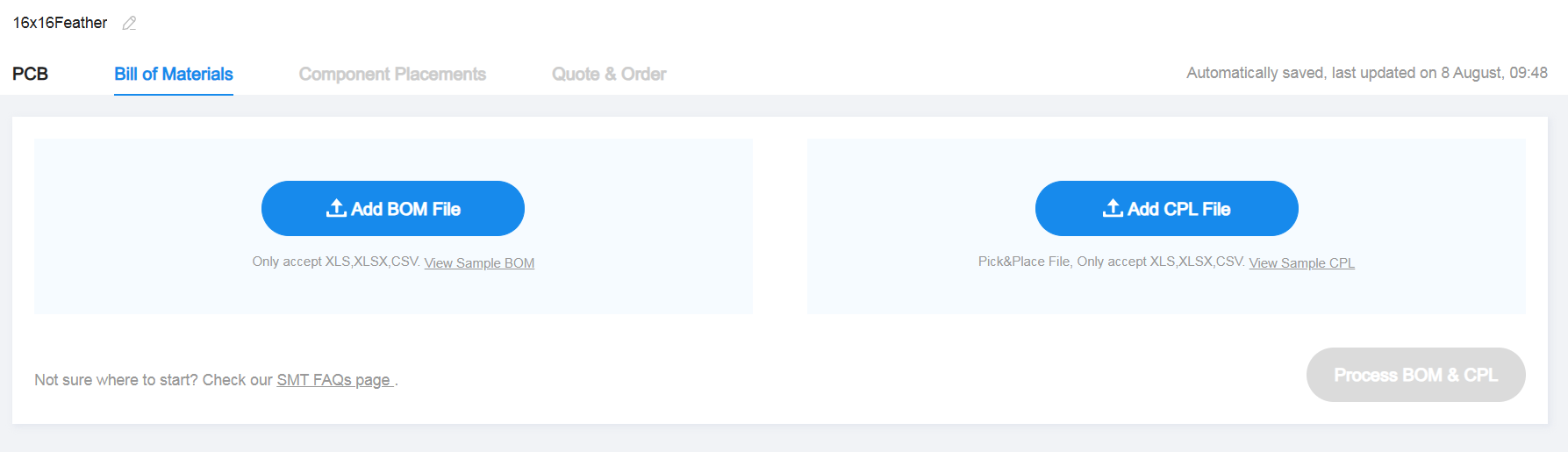
Upload the Bill of Materials (BOM) (download) and Component Placement (CPL) (download) files
- Review the matched parts, making sure all are selected and none are in shortfall.
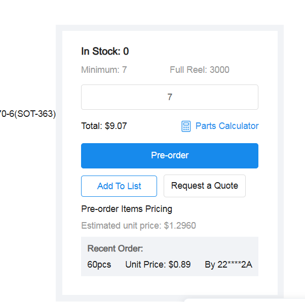
If any parts are in shortfall, you can either order them to your parts library (so that you may order the board when the components are in stock) or order them to your address and solder them yourself. To add shortfall components to your part library, click the Search icon in the Matched Part Detail of the shortfall part.
A window will show up with a list of parts matching the shortfall. Check that the first part patches the description, and click on it.
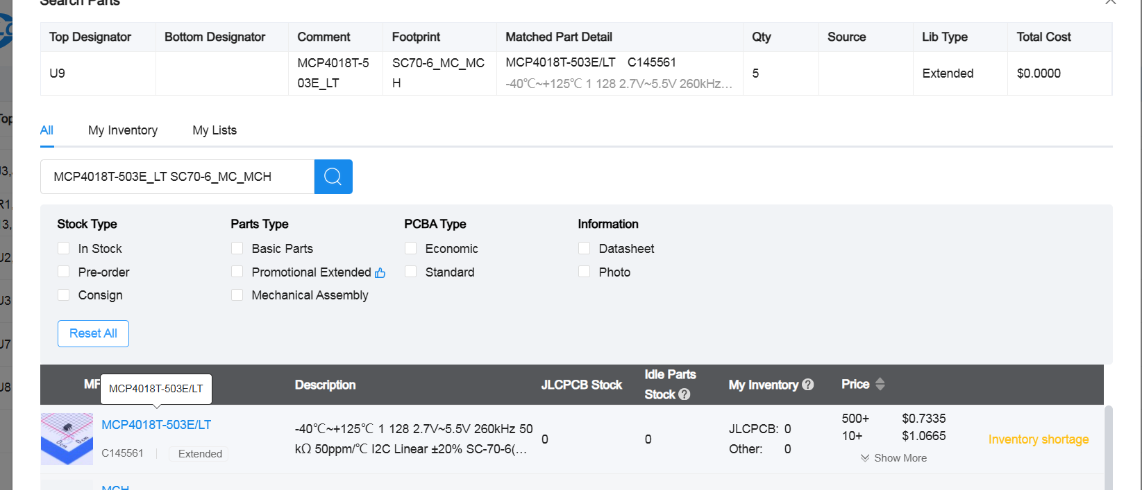
Change the QTY to the desired number of components (at least covering what is in shortfall, but you can always order more to be safe) and preorder.
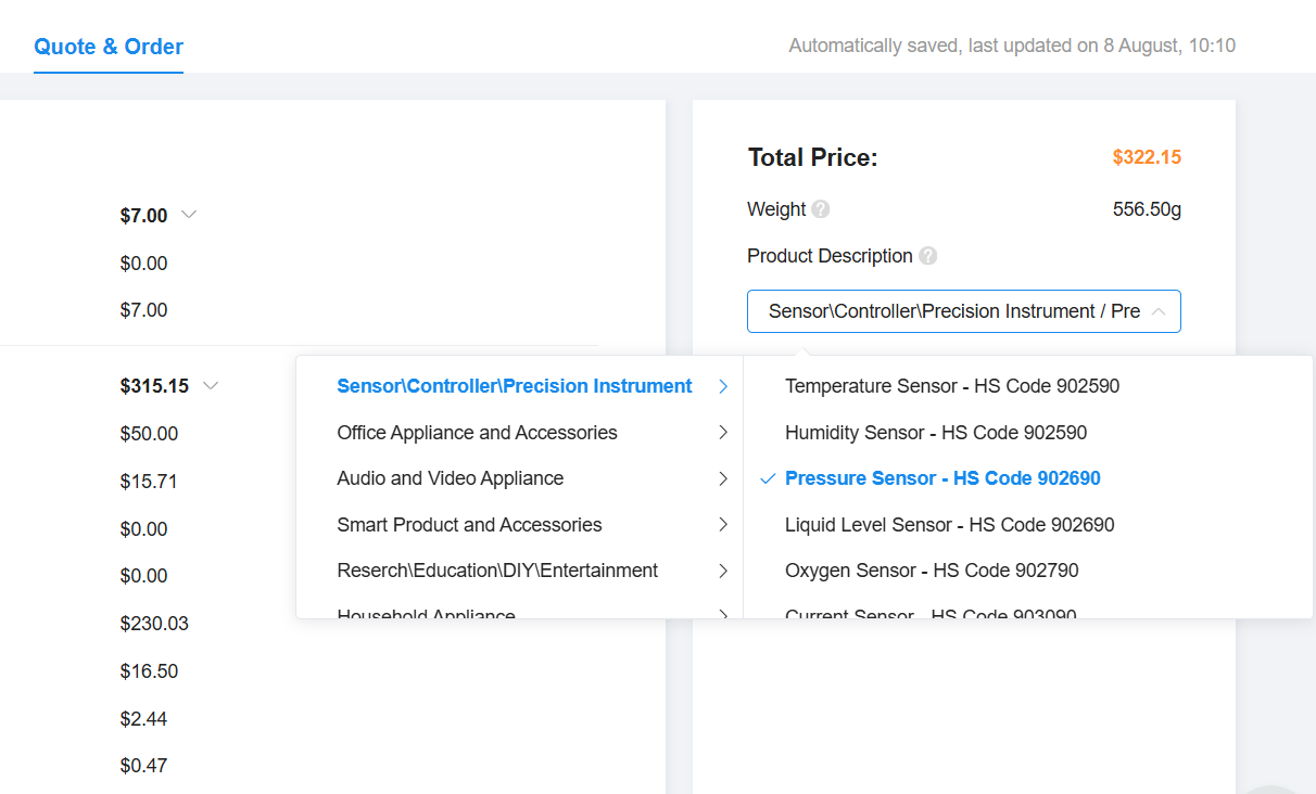
- Click "next" on component placements, and on the quote and order tab select "Sensor/Controller/Precision Instrument -> Pressure Sensors" for the product description. Click save to cart and complete order.
Flexible Printed Circuit Board (FPCB) Electrodes
The gloves use flexible PCBs (FPCBs) to route sensing electrodes along the contour of the hand. Two FPCBs are required per glove—one for the top array and one for the bottom array.
You must place two separate orders: one for the top PCB and one for the bottom PCB.
Our reference designs are available in large and small sizes, or you can create your own using the design tool above.
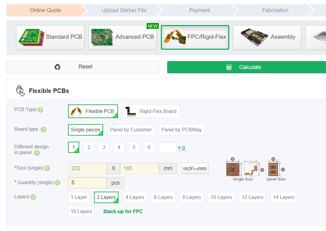
We recommend using the PCBWay Flex PCB Instant Quote Tool to manufacture both top and bottom boards.
Order the Top PCB
-
Open the Flex PCB Instant Quote Tool.
-
Enter the manufacturing details for your size:
- Large: download details (PDF)
- Small: download details (PDF)
(Follow the "Special Request" instructions exactly as listed in the PDF.)
-
Quantity tip: The number you select equals the number of final sensors you'll have. For example, ordering 2 top PCBs yields enough for 2 sensors (one glove pair).
-
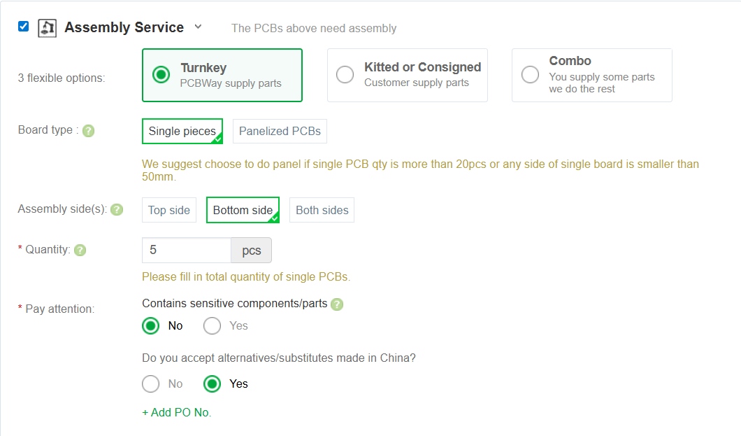
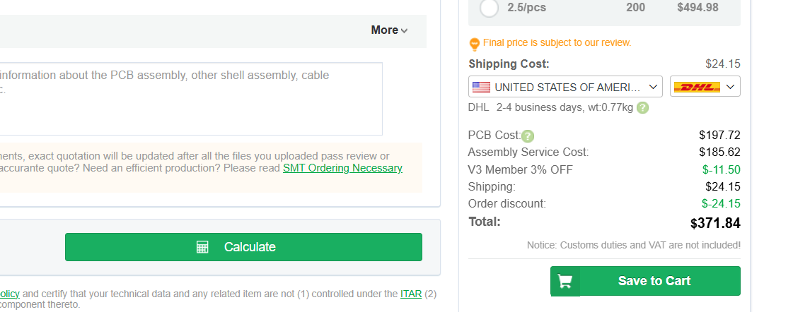
If you want ready-to-use PCBs, add assembly service. For top PCBs, components are assembled on the bottom side.
-
Click Calculate, select your shipping speed, and save the order to your cart.
-
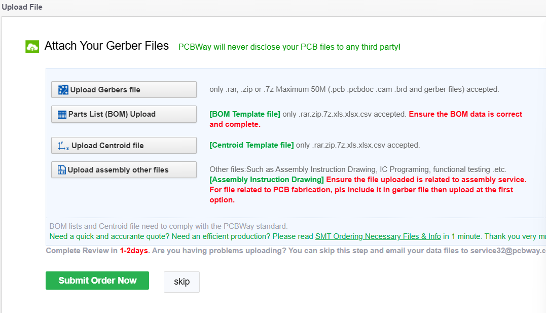
Upload the required files for your chosen size:
-
Once all files are uploaded, click Submit Order Now.
Order the Bottom PCB
Repeat the same process, but with bottom PCB details and files:
- Manufacturing details: Large | Small
- Assembly side: Top
- Gerbers: Large | Small
- BOM: Download
- Centroid: Large | Small
Other Materials for Assembly
For the readout circuit:
- Adafruit Huzzah ESP32 Feather Board - If operating wirelessly, two are needed per one glove.
- 2.54 mm header pins (for connecting to the ESP32 Microcontroller)
- 0.5 mm Pitch Flex Cables (16-pin) (for connecting to the sensor. 2 needed per glove.)
- PLA Filament (for printing the circuit enclosure)
- Velcro Wrist Strap (one per glove)
- 3.7v LiPo Batteries (one per glove)
For the sensor:
- Adhesive-Backed Silicone Rubber (McMaster 9010K51). A 24" x 24" sheet makes about 4 sensors (two pairs of gloves)
- Pressure-sensitive Conductive Sheet (Velostat)
- Anti-slip Gloves
- Super Glue
Manufacturing + Assembly Guide
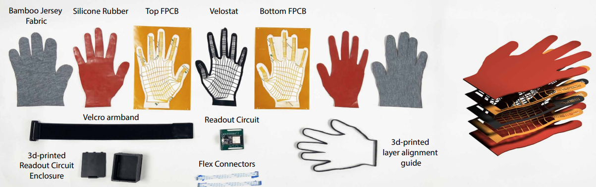
Before starting, make sure you've completed the ordering steps above to obtain all required materials. A visual overview of the necessary materials is shown below:
To build the gloves, you will need access to:
- A laser cutter (CO₂ recommended)
- A 3D printer (PLA filament recommended)
If you do not have access to these tools, you may use external vendors. We provide examples for laser cutting and 3D printing in the relevant sections below.
Step 1: Laser Cut Supporting Layers
You will cut two adhesive-backed silicone rubber layers and one Velostat layer.
If you don't have a laser cutter, you can outsource the job to:
Instructions:
-
Download the appropriate SVG outline:
-
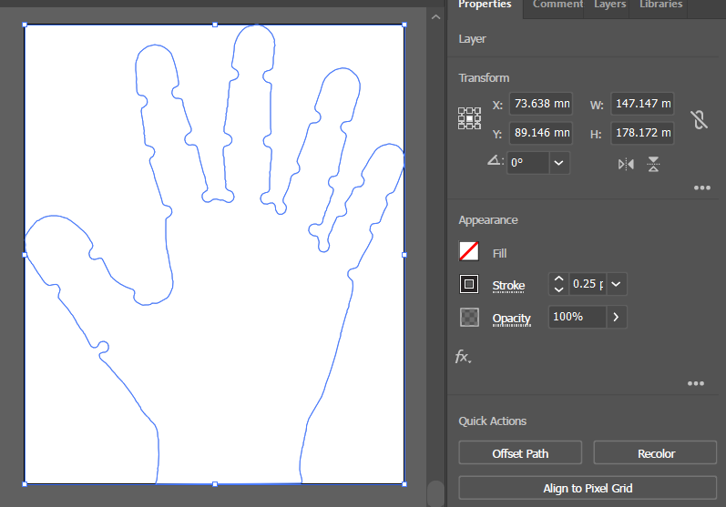
Open the SVG in your laser cutter software. Ensure the document units are set to millimeters (mm). Verify the dimensions:
- Small outline height: 178.17 mm
- Large outline height: 209.75 mm
-
Refer to
lasercutting.txtfor recommended power, speed, and frequency settings. -
Cut the following:
-
Two silicone rubber layers:
- One in the default orientation
- One mirrored horizontally
-
One Velostat layer
-
Step 2: 3D Print Enclosure and Alignment Guide
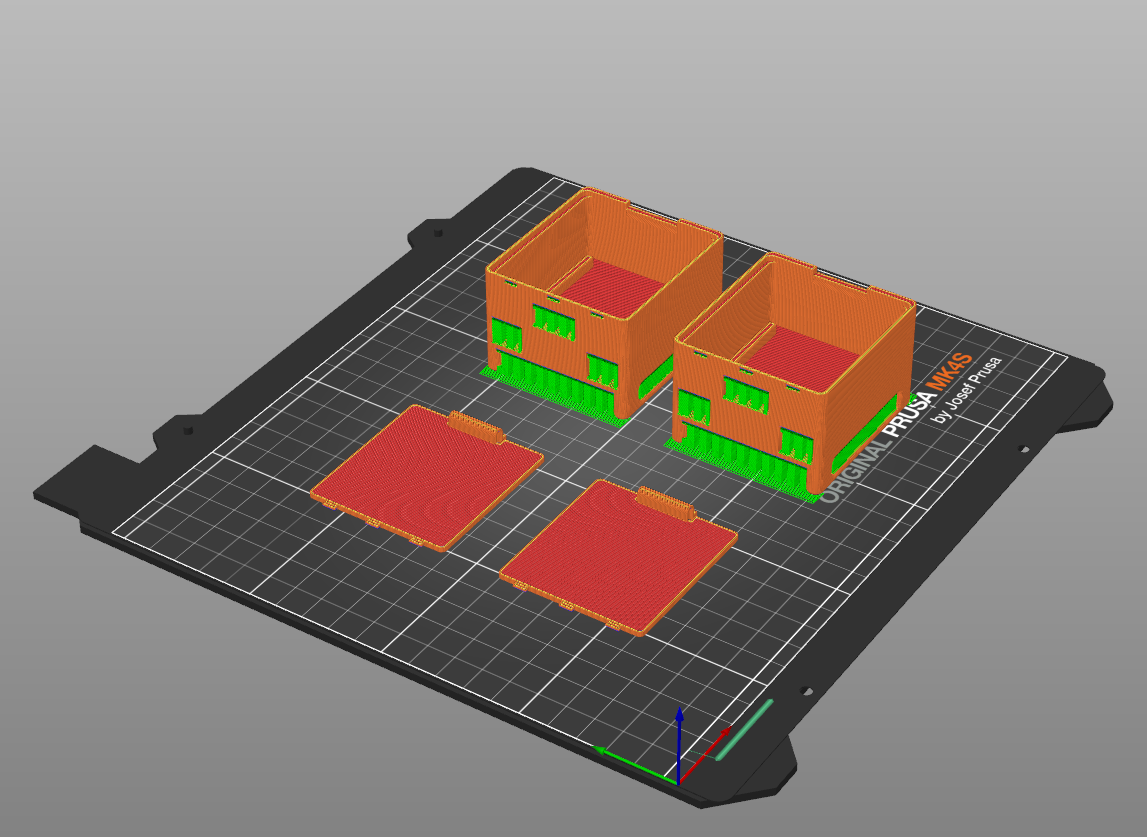
If you don't have a 3d printer, you can outsource the job to Xometry
Instructions:
-
Download the STL files:
-
Print using PLA filament.
- Add supports (automatic painting for overhang > 25% is sufficient).
Step 3: Align Sensor Layers and Attach Cables
⚠️ This is the most delicate step. Work carefully to avoid damaging the layers.
Instructions:
-
Place one silicone rubber PCB layer (adhesive side up) into the alignment nest.
- Remove adhesive backing.
- Place the Velostat layer on top and press along the edges.
- Remove the two-layer stack from the nest.
-
Flip the nest over. Place the second PCB layer adhesive side up.
- Remove adhesive backing.
- Place the two-layer stack (from step 1) on top, Velostat side down.
- Press edges to seal. Remove the three-layer stack.
-
Place an adhesive-backed silicone rubber layer into the nest, adhesive side up.
- Remove backing.
- Place the three-layer stack on top. Press edges to seal. Remove four-layer stack.
-
Flip the nest. Place the second silicone rubber layer adhesive side up.
- Remove backing.
- Place the four-layer stack PCB side down. Press edges to seal. Remove the final five-layer sensor assembly.
-
Locate the flex connectors on the top and bottom sensor layers.
- Gently flip them up, insert a flex cable into each connector, then flip down to lock.
Step 4: Glue Sensor into Glove
Instructions:
-
Turn the glove inside out and wear it, with the grippy side touching your palm.
-
Place the sensor on the table in the same orientation as your hand. You can verify the orientation by placing the hand wearing the glove onto the sensor and making sure the thumbs and pinky fingers touch.
-
Apply super glue to the tips of each sensor finger.
- Touch the glove fingertips to the glued sensor tips.
- Hold in place for ~45 seconds.
-
Remove the glove, then flip it inside out again so that the sensor is now inside.
Step 5: Connect Glove to Readout Circuit
Instructions:
-
Solder the female header pins onto the same side of the readout circuit that contains the flex cable connectors.
- Insert the Adafruit Feather ESP32 microcontroller into the headers, aligning with the back pins (some pins on USB port side will hang free - this is expected).
-
Place the glove grippy side up on the table.
-
Thread each flex cable through the corresponding slots in the 3D-printed enclosure.
-
Connect the flex cables to the readout circuit's flex connectors.
-
Fit the readout circuit firmly into the enclosure base and close the lid.
-
Flip the enclosure over and thread a Velcro armband through the bottom slots for secure attachment.
Recording Data
Before recording with your gloves, you'll need to:
- Install the required software and firmware.
- Upload firmware to your microcontrollers.
- Configure the devices using the backend and GUI tools.
🚀 Quick Start (For Pre-Assembled Gloves)
If you already have a working set of gloves (you did not build them yourself), you can skip straight to recording:
-
Clone and install WiReSensBackend.
-
Plug the receiver microcontroller into your laptop and power the transmitter microcontroller (the one connected to the glove) either with a LiPo battery or by plugging it into a power source via USB cable.
-
Activate your Python environment.
-
Run port detection:
python autoDetectPort.py [--small] [--left] [--right]--small= if using small gloves--left/--right= if recording from only one glove
-
If successful, you'll see:
✅ Success: Config file used and ports discovered. -
Start recording:
python recordOnly.py [--small] [--left] [--right]
👉 That's it! You're ready to record.
👉 If you want to calibrate your gloves or use the Web GUI, continue with the sections below.
Install Software
Follow the installation instructions from the following repositories:
-
WiSensToolkit: Firmware for the microcontrollers
-
WiReSensBackend: Python library for interfacing with sensors
-
WiReSensWeb (Optional): Real-time visualizer and GUI.
- Use it online at https://wi-re-sens-web.vercel.app/
- Or set it up locally for offline access.
Upload Firmware
(skip if gloves already shipped pre-flashed)
Transmitter vs. Receiver
- Transmitter: ESP32 connected to the readout circuit and glove sensor via flex cables.
- Receiver: Standalone ESP32 that receives wireless data from the transmitter and forwards it to your laptop.
👉 If using ESP-NOW (recommended: fastest, longest range, most portable), upload firmware to both transmitter and receiver.
👉 If using USB-Serial, WiFi, or Bluetooth, upload firmware to the transmitter only.
Upload Receiver Firmware
-
Connect an ESP32 (receiver) to your laptop via USB.
-
In VSCode, open the WiSensToolkit folder.
- Set the serial port:
Ctrl + Shift + P→ search forpioarduino: set project port→ select the port (e.g., CP210x USB to UART Bridge).
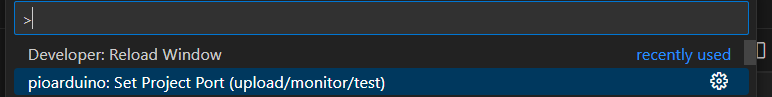
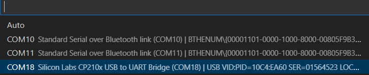
- Set the serial port:
-
Open
platformio.iniand set:build_src_filter = +<espReceive.cpp> -<scanArray.cpp> -<noCalibrate.cpp> -
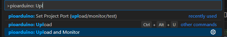
Upload with
pioarduino: Upload and monitor.
-
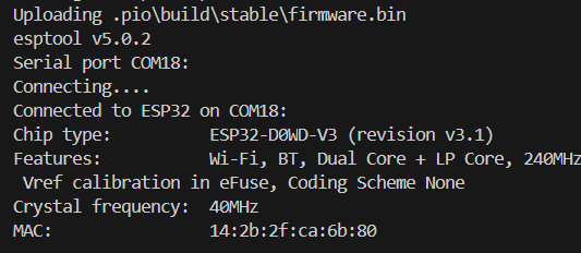
In the serial monitor, copy the receiver's MAC address and convert each hex pair to decimal (use this converter).
Example:14:2b:2f:ca:6b:80→20:43:47:202:107:128
-
Disconnect the receiver.
Upload Transmitter Firmware
-
Connect the ESP32 attached to the glove readout circuit.
-
In
platformio.ini, set:build_src_filter = -<espReceive.cpp> -<scanArray.cpp> +<noCalibrate.cpp> -
Upload with the same steps as the receiver.
Configure Transmitter
Configuration uses WiReSensBackend and the Web GUI:
-
Keep the transmitter connected via USB.
-
Start the backend:
python startBackend.py -
Open the GUI: https://wi-re-sens-web.vercel.app/ (or
localhost:3000if local).
-
-
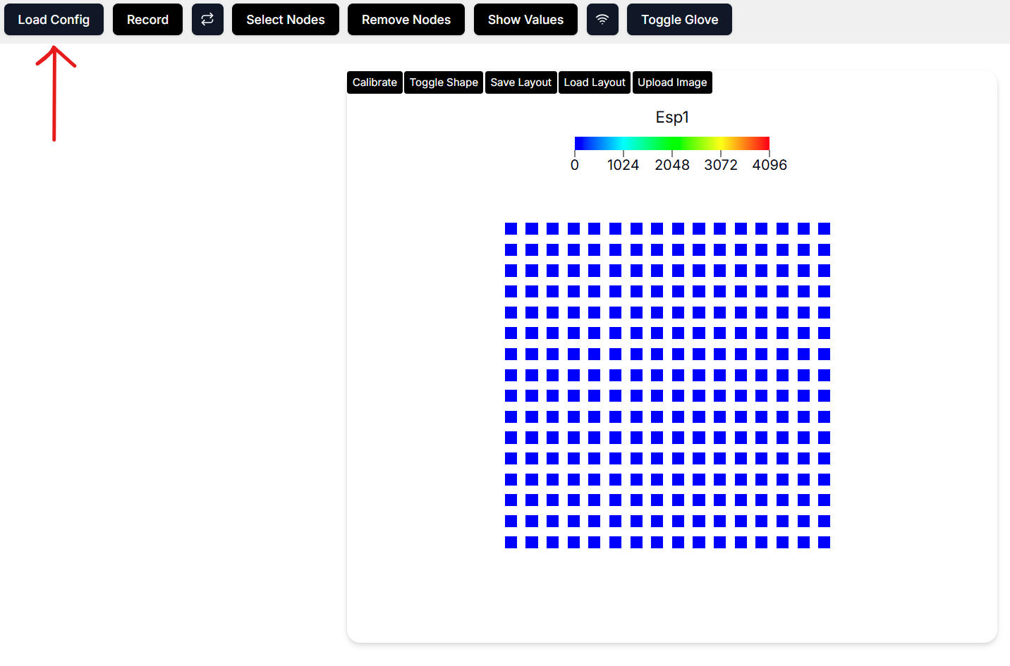
In the GUI, click Load Config and select the JSON file from the backend's
configsfolder (e.g.,oneGloveTransmitter{Left|Right}.json).
-
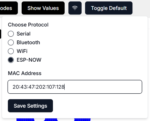
Click the Wireless Comms (🛜) button and paste the converted decimal MAC address from the receiver step. Save settings.
-
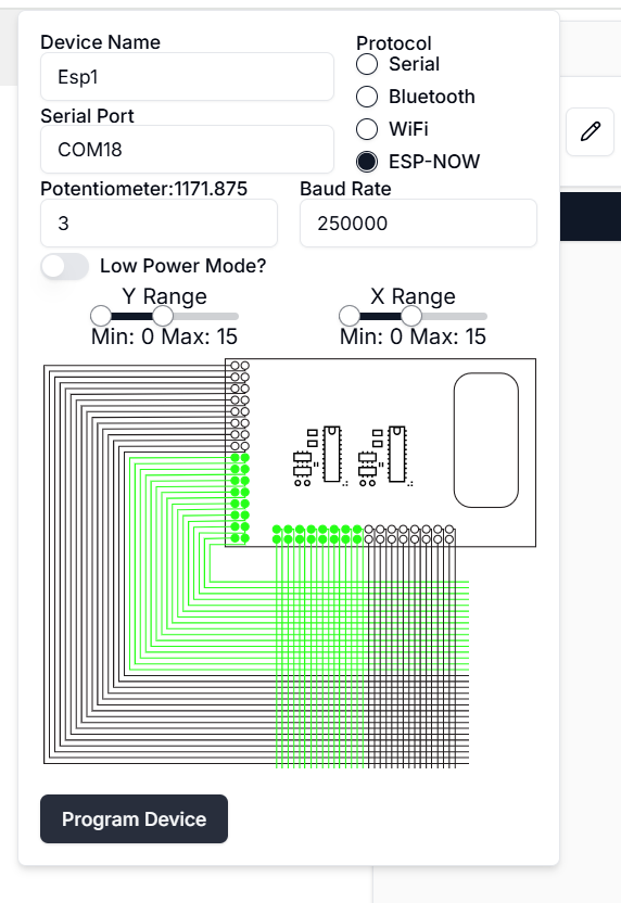
Open the Device Panel → Edit Device, set the serial port to the transmitter's port, and click Program Device.
-
The transmitter can now run on USB or a LiPo battery.
Recording via Web GUI
- Connect the receiver to your laptop.
- Load the receiver config JSON (e.g.,
oneGloveSerialReceiver{Left|Right}{Large|Small}.json). - In the device panel, set the receiver's serial port and click Program Device.
- Click Record in the GUI.
Calibrating the Gloves
-
Ensure both transmitter and receiver are plugged in.
-
Install the Serial Monitor extension for VSCode.
-
In the GUI, switch to Default Visualization and start recording to see glove signals.
-
In the serial monitor, connect to the transmitter's port at 250000 baud.

-
Noise Calibration:
- Type
noiseand press Enter. - Wait 1 min (no pressure needed). You'll see "finished noise calibration" when done.
- Type
-
Sensitivity Calibration:
- Type
minsand press Enter. - Apply max pressure to every area of the glove until signals saturate (≈5 min).
- Type
stopMinswhen finished.
- Type
-
Reset the transmitter (button press or unplug/replug). Data is now calibrated.
Recording via Backend (Headless)
-
In WiReSensBackend, activate your Python environment.
-
With receiver microcontrollers connected to your laptop and transmitter microcontrollers powered, run port detection:
python autoDetectPort.py [--small] [--left] [--right]-
--small= using small gloves -
--left/--right= only record one glove -
Success message:
✅ Success: Config file used and ports discovered.
-
-
Record:
python recordOnly.py [--small] [--left] [--right]
Creating MP4 Videos of Tactile Recordings
The script createViz.py generates an MP4 visualization of tactile recordings from one or both glove HDF5 files.
Usage
python createViz.py [--left_h5 LEFT_FILE] [--right_h5 RIGHT_FILE] [--small] [--output OUTPUT_FILE]
Arguments
-
--left_h5 <path>
Path to the HDF5 file for the left glove.
Example:--left_h5 recordings/left_glove.hdf5 -
--right_h5 <path>
Path to the HDF5 file for the right glove.
Example:--right_h5 recordings/right_glove.hdf5 -
--small
Use the smaller glove SVG visualization instead of the default large glove.
Example:--small -
--output <filename>
Name of the output MP4 file (default:tactile_overlay_cuda.mp4).
Example:--output my_tactile_video.mp4
Requirements
- You must provide at least one of
--left_h5or--right_h5.
Example Commands
-
Visualize the left glove only:
python createViz.py --left_h5 data/left.hdf5 -
Visualize both gloves and save to a custom file:
python createViz.py --left_h5 recordings/left.hdf5 --right_h5 recordings/right.hdf5 --output both_gloves.mp4 -
Use the smaller glove visualization:
python createViz.py --right_h5 recordings/right.hdf5 --small